Cable Management vs. Airflow Management: How to Reconcile the Two20 min read
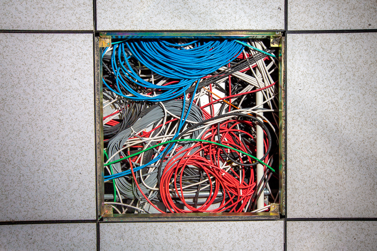
First and foremost, we should never have to choose between good cable management and good airflow management. After all, poor cable management may produce poor airflow management, and therefore, effective cable management is a critical contributor to effective airflow management. Granted, there are some aspects of cable management that may represent challenges to airflow management, but only when the two tasks are attacked in isolation. When design and implementation are pursued as a single and integrated project, cable management will support the goals of airflow management.
Knowing the Goals
What are the goals of airflow management? The obvious primary objective is separation of supply air mass and return air mass, resulting in the widely reported benefits of lower fan energy costs, increased CRAC efficiency, as well as increased chiller efficiency and access to more hours of free cooling. In addition, there are associated objectives related to maintaining cumulative pressure head that cooling unit fans and IT equipment fans operate below some threshold, thereby preventing that non-linear increase in fan energy. Remember, while the rpm:kW ratio is a cube function, the pressure head:kW ratio is still a squared function. Therefore, the goals of cable management should include maintaining hot and cold separation and maintaining acceptable system pressure impedances along with minimizing data transmission impedance and facilitating easy management of moves, adds and changes.
Cabling Under the Raised Floor
The oldest and most basic confluence of cable management and airflow management is where under-floor space is shared for cable distribution and cool air distribution. Floor penetrations for routing cables from under the floor into server cabinets can break down the separation between cool air masses and warm air masses, producing bypass airflow. Figure 1 illustrates how dramatic the bypass airflow production can be. The server cabinets have been hidden to make it easier to see the hot aisle bypass.
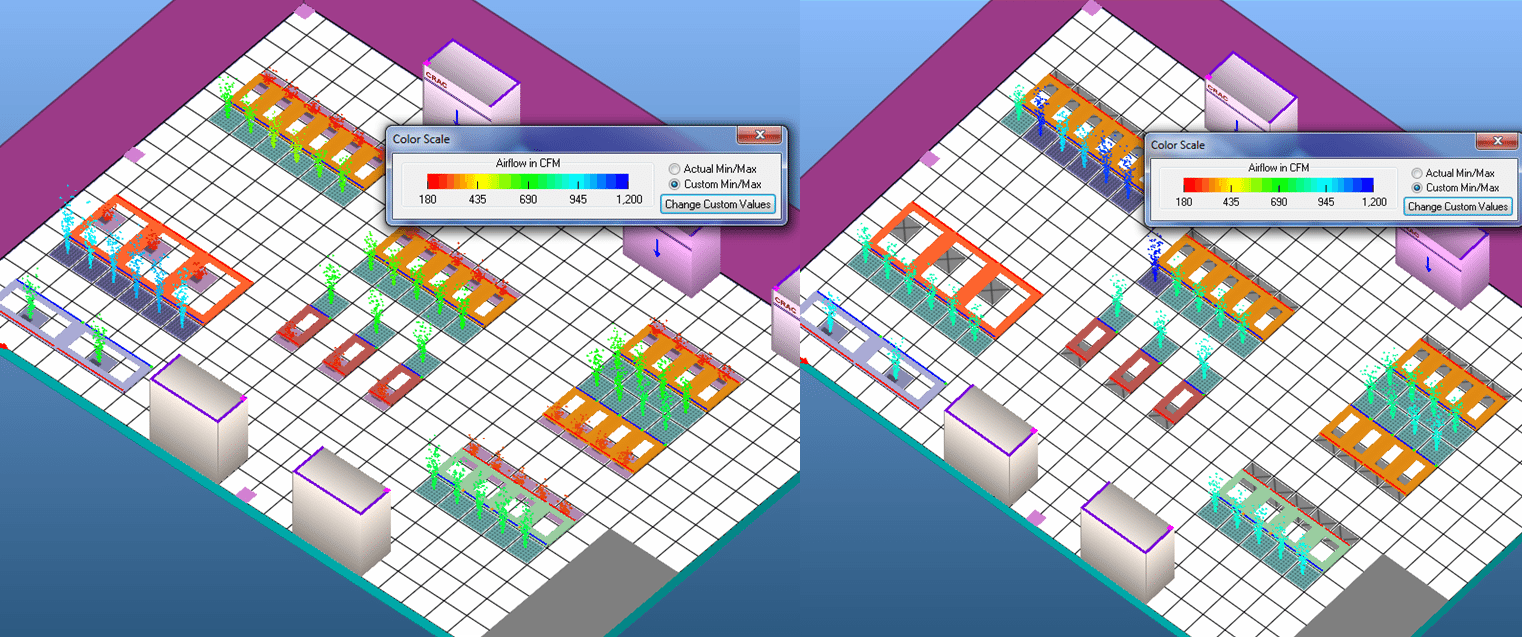
Figure 1: CFD Comparison of Open Cable Penetrations versus Sealed Cable Penetrations
In this particular model, plugging all the bypass holes produced an average 90% increase in airflow per perforated floor tile. That increased airflow could mitigate any hot spot issues. In this example, it would allow a 400 watt per cabinet increase in IT load, or 13.2 kW total in this small 1300 ft2 room with 33 cabinets, enough to add a fully loaded blade chassis to 24 of the 33 cabinets. The other cable management concern under the floor relevant to airflow management involves the volume of cable and the direction in which it is deployed. First, underfloor cable pathway should always be arranged so the runs are located in hot aisles and are parallel to the airflow direction, and should be located close to the underside of the raised floor. The layout depicted in Figure 1 obviously does not comply with this basic best practice.
Overhead Cabling
If a data center manager is faced with the situation in Figure 1 and if moving the perimeter cooling units to adjacent walls or reorienting the rows of server cabinets 90˚is not practical, there are other alternatives. For example you could raise the cooling units on standard pedestals, replace all the perforated floor tiles with solid tiles and add chimneys and solid rear doors to all the cabinets. Even that exercise will be energy and budget intensive, which is why doing this correctly in the first place, is so important. If it is not practical to eliminate the raised floor, then moving cable distribution to overhead pathway and reserving the underfloor space for air distribution is an effective strategy. This can reduce the pressure head against which the cooling unit fans are operating. Again, it is important to try to get long runs of pathway that are out on the data floor to run parallel to the return airflow paths. In addition, vertical orientation plays a role in either enhancing or diminishing effective hot and cold aisle separation. In Figure 2, the model on the left has the pathway biased toward the ceiling; whereas the model on the right has the pathway biased toward the cabinets.
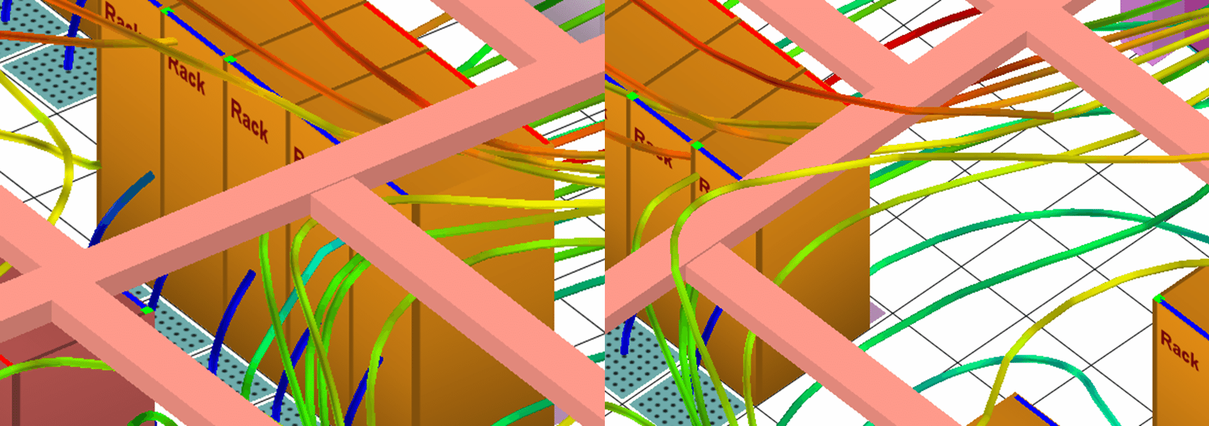
Figure 2: Effect of Overhead Cable Pathway on Return Air Isolation
With the pathway closer to the cabinets, we see more of the return air traveling over the pathway into a return air path. When the pathway is oriented higher in the room, more return air is encouraged to re-circulate under the pathway and contaminate the cold aisle.
Cabling Inside Server Cabinets
While it is important to attend to the effect of cable management in the room on the effectiveness and efficiency of the airflow management strategy, these topics have been discussed for years as part of most data center standards and best practices, and are generally accepted and practiced throughout the industry. However, cable management inside the server cabinet often falls into the out-of-sight-out-of mind paradigm and frequently contributes to significant compromises of the best intentions for airflow management.
The importance of effectively managing cabling in the rear of server cabinets should be obvious to most industry practitioners, despite the rather wide variation of actual execution. As far back as 2002, research attributed thermal repercussions from poor cable management in the rear of cabinets. According to the research, the possibility of component temperature rises as much as 9˚F due to airflow blockages from cable management arms or dense cable bundles in the airflow path, particularly in 1U form factors. Twenty years later, the impact is less likely to be overheating than running up the electric bill with higher server fan energy. More recently, research suggesting that 0.15” H2O column might be the threshold for pressure added to IT equipment fan loads by obstructions such as cable bundles in the rears of cabinets, before flow rates dramatically reduce or fan energy costs dramatically increase. For these reasons, as cabling density increases, regardless of heat/power density, we strongly recommend deploying equipment in cabinets wider than the standard 24” or 500mm footprint.
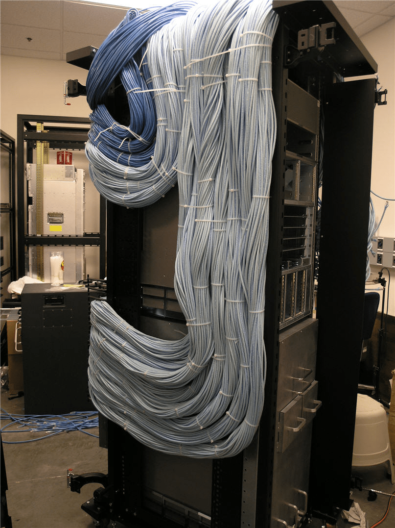
Figure 3: Cable Bundle Example
Avoiding cable bundle airflow obstructions in the rear of racks is not the only airflow management issue arising from cable management challenges within the cabinet. Figure 3 illustrates the scope of the problem with the volume of cables in a single rack with two high port-count large switches. There is a variety of IT equipment, mostly switches, which have non-standard airflow patterns directly attributed to cable management. There are switches that breathe side-to-side to facilitate managing the cable connections on the front of the switch. In addition, some of these switches have hot-swappable components on one side of the front, so all the cable bundles need to be routed to the other side of the switch, which is typically the fan in-take side. Cable management is critical in these instances to avoid blocking the fan in-take vents as well as leaving space on that side of the switch for an airflow ingress path. There are various ways of addressing this condition, but a chimney cabinet that allows in-take air to enter both the front and the rear of the cabinet is one highly effective method to minimize the impact of the large cable bundles.
Other Considerations
There are other airflow anomalies mostly attributable to the various OEM’s desire to offer a user-friendly solution for cable connections and managing moves, adds and changes. The results of this motive are IT boxes, typically in 1U and 2U form factors, that may breathe front to one side or the other, front to both sides, or both sides to rear. There is also equipment that breathes rear to front, but more often than not these situations are the result of equipment merely being installed backwards. Such backwards installation, however, is very logical, as it allows the user easy access to connecting and managing cables which would otherwise be terminated in the rear of the cabinet, often nearly half-way into the cabinet from the rear door. While it may be easy to say we should just install this equipment correctly and be done with it – that’s only easy to say for someone who isn’t responsible for maintaining the network connectivity. A better solution is to orient the equipment according to the proven paths for managing connectivity, and then accommodate airflow with rack-mount shells that surround these switches. This will redirect the airflow so that at the cabinet level, everything is still behaving front-to-rear. There are plenty of solutions available for most popular non-standard breathing equipment and if you’ve managed to specify something that no one has seen before, it’s easy enough to get something made down at your local sheet metal shop. One note of caution: if you’re getting work done by a local shop, you might want to have the design confirmed in a CFD model before trusting your IT equipment into its care.
It’s my contention that there is no good reason for compromising good airflow management practices and that solving cable management challenges needs to be a part of the overall airflow management initiative. As always, I look forward to hearing from readers who have gone out and found some piece of equipment that breathes top-to-front, just to keep me from thinking I’ve wrapped up this subject.
The industry's easiest to install containment!
AisleLok® solutions are designed to enhance airflow management,
improve cooling efficiency and reduce energy costs.
The industry's easiest to install containment!
AisleLok® solutions are designed to enhance airflow management,
improve cooling efficiency and reduce energy costs.

Ian Seaton
Data Center Consultant
Let's keep in touch!


0 Comments