The More Commonly Known Delta Ts in Data Center Cooling17 min read
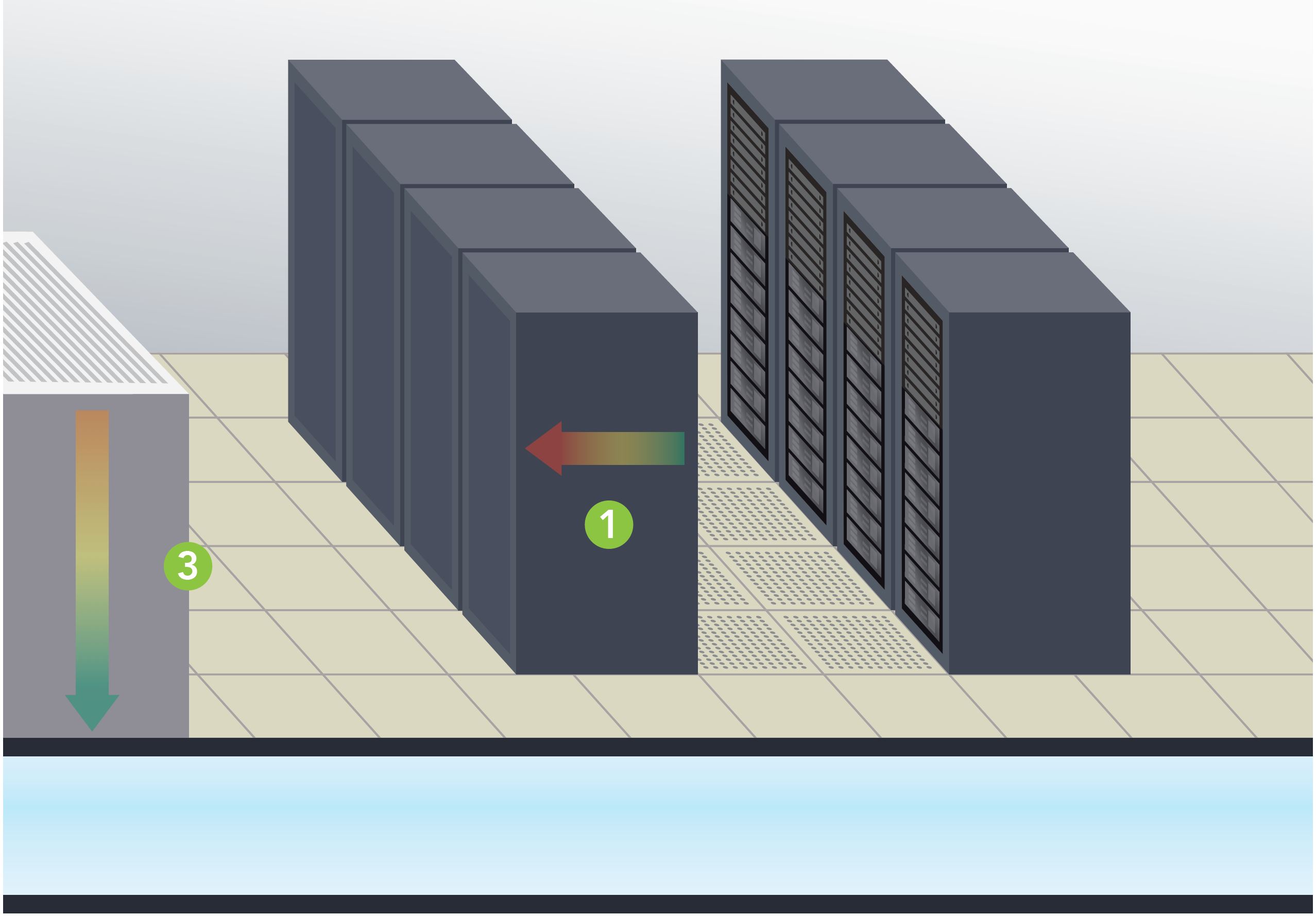
There is not just THE ΔT and there are not even just two ΔTs in the data center. As a matter of fact, there are four different ΔTs which contribute to the health of the data center. Two of these temperature differentials are frequently considered as a single metric: the temperature rise of air as it passes through IT equipment, picking up and removing the heat produced within that equipment and the temperature differential across the cooling equipment cooling coils, or the difference between supply and return air temperatures. Frequently these two ΔTs are discussed as “The ΔT,” but there are good reasons for considering them separately and monitoring how they may actually differ.
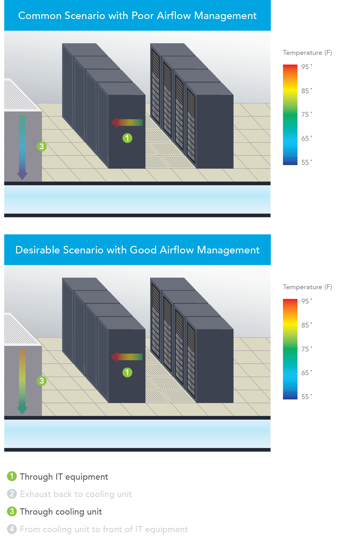
Through IT Equipment
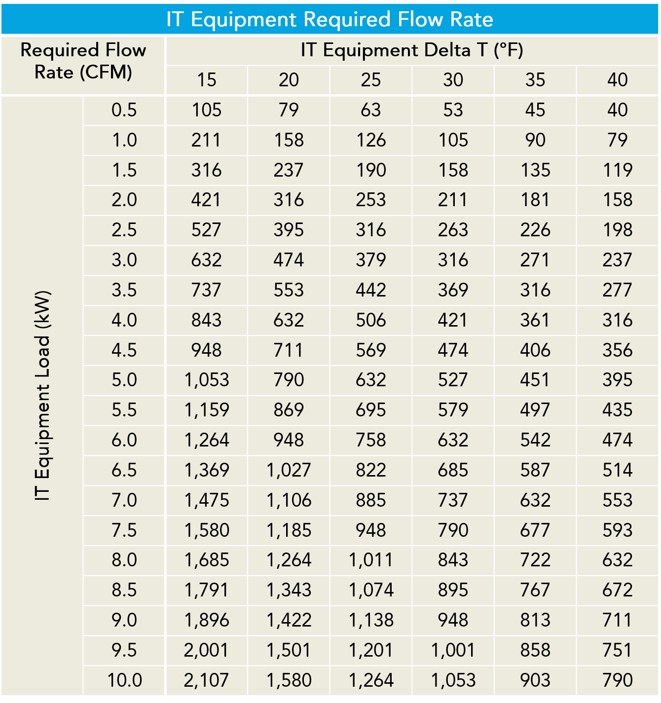
Typically ΔT is discussed in our industry as a single metric or phenomena and, depending on who is doing the talking, that single metric is based on the temperature drop across the cooling equipment or the temperature rise across the IT equipment. There are many reasons why these two values may be different, but those reasons will generally fall into two categories – the return air to the cooling units is being cooled by bypass airflow or it is being warmed due to hot air re-circulation. Regardless of the airflow management effectiveness in the data center, the IT equipment airflow temperature rise will be the constant.1 There is a fixed relationship between airflow, temperature differential and heat, shown in Table 1 below, but simply stated as ΔT = 3.1W ÷ CFM, where 3.1 = a constant coefficient at sea level and W = watts and CFM = cubic feet per minute airflow. That coefficient changes for calculations at higher altitudes, for calculations in Celsius, for airflow measurements in liters per second or cubic meters per hour, and for heat measured in kW or BTU. Whatever terms or units are being considered, there is a fixed relationship between these three factors. In actual applications, the ΔT across IT equipment typically ranges from around 20˚F up to around 35˚F, depending on the type of equipment. For example, blade servers will typically produce a higher ΔT than pizza box servers. The 20˚F temperature rise illustrated in Figure 1 is representative of many commercial 2U rack mount servers.
Through Cooling Units
In some cases, particularly when the conversation is being conducted among mechanical or facilities engineering participants, THE ΔT is the temperature drop across the cooling coils, or across whatever is removing the heat from the data center air, such adiabatic media or energy recovery wheel. Ideally, this delta should be the same as the delta across the IT equipment, indicating that the cooling resource is perfectly matched to the heat load it is serving. That is the ideal, but only rarely approached. First, it is useful to understand some of the design factors accounting for temperature differences across the cooling resource. Most simply, in legacy DX CRAC units, that temperature drop was typically fixed somewhere in the neighborhood of 18˚F and there was not much allowance for variation from that baseline ΔT. For example, increases in return air temperature resulted in an associated increase in supply air temperature, so a 5˚F increase in return air temperature might result in a 3˚ or 4˚ increase in the supply temperature; the overall ΔT would increase slightly, but nowhere near the proportion possible with water-cooled coils. Most of the name-brand water-cooled CRAH units today can remove heat equivalent to anywhere from 45˚ up to 65˚F temperature drop across the cooling coils. Given the mathematical relationship between heat, airflow and ΔT previously discussed (CFM = 3.1W/ΔT), the higher ΔT across those coils means we are removing more heat and therefore the CRAH unit is operating much more efficiently. Normally, we would say that is a good thing, except if the ΔT across the IT load is still only 20˚F, then we are not effectively removing any more heat; rather, we are just accommodating the inefficiency of the overall airflow management scheme.
The ΔT across the cooling source is also affected by set points. For example, if there is a lot of bypass airflow it is conceivable (this happens much more frequently than folks will admit outside the friendly confines of their local pub or tavern) that the return air can actually be below the set point and therefore is returned to the data center without any additional heat being removed: ΔT = zero. Furthermore, with a normal return set point, similar to a home or office thermostat setting, the CRAHs will be working to bring the data center temperature down to that set point, resulting in ΔTs which could range from 0 up to over 20˚F. Finally, if the CRAHs are operating with a fixed supply temperature, the ΔT could range from 20˚-35˚ based on the types of servers deployed in that space, or the cooling coils could see less than 10˚F if there is a lot of wasted surplus cooling in the space, up to over 40˚F if there is a cumulative hot air re-circulation effect. The remaining, less discussed, two areas of ΔT can provide assistance in understanding differences between IT and coil ΔTs and suggest possible remediating strategies.
1There will be some conditions in which the ΔT will not remain constant, especially with the proliferation of variable speed fans in today’s IT equipment. When inlet temperatures are allowed to exceed the maximum recommended threshold and move toward the upper allowable levels, many servers will ramp up fans to protect the equipment, thereby reducing the ΔT through the IT equipment. Additionally, with the increased adoption of cloud-based data centers, whole large caches of work can be transferred between data centers with the resultant increased work load producing higher chip temperatures and, therefore, higher ΔTs. Nevertheless, in normal conditions, the equipment ΔT remains a constant.
Real-time monitoring, data-driven optimization.
Immersive software, innovative sensors and expert thermal services to monitor,
manage, and maximize the power and cooling infrastructure for critical
data center environments.
Real-time monitoring, data-driven optimization.
Immersive software, innovative sensors and expert thermal services to monitor, manage, and maximize the power and cooling infrastructure for critical data center environments.


0 Comments